03 December, 2018

Interior Mapping Shader for Unity3D

After doing yesterdays writeup i went and cleaned up my unity shader for interior mapping.

But as you can see an oddity popped up. In the preview (bottom right) everything looks fine and dandy, but in the scene it suddenly gets uggly jagged edges. this has apprently to do with my choice of using tex2D for texture sampling, which is trying to use MIP-maps. Due to the procedural nature of our shader this fails miserably though. by replacing the lookup with tex2Dlod(tex,float4(uv,0,0)) this is rectified. This always samples the biggest resolution, which results in a performance hit, but fixes those ugly edges.

I'm not a shader artist, i just have fun fiddling with shaders, and i know that there are techniques to fix this properly and without performance hit (even applying AA across the seams) but to this day i cant wrap my head around those, so i cant modify my shader to utilize them. maybe someone else can help me there. anyway here is the code:


Shader "Custom/Interior Mapping Raytrace" {
 Properties{
  _Color("Color", Color) = (1,1,1,1)
  _TextureAtlas("Texture Atlas(RGB)",2D) = "white"{}
 }
  SubShader{
   Tags { "RenderType" = "Opaque" }
   LOD 200

   CGPROGRAM
  #pragma surface surf StandardSpecular

  // Use shader model 3.0 target, to get nicer looking lighting
  #pragma target 3.0

  sampler2D _TextureAtlas;

  struct Input {
   float3 viewDir;
   float3 worldPos;
  };

  fixed4 _Color;

  // Add instancing support for this shader. You need to check 'Enable Instancing' on materials that use the shader.
  // See https://docs.unity3d.com/Manual/GPUInstancing.html for more information about instancing.
  // #pragma instancing_options assumeuniformscaling
  UNITY_INSTANCING_BUFFER_START(Props)
   // put more per-instance properties here
  UNITY_INSTANCING_BUFFER_END(Props)

  //simplified intersection for axis aligned planes which only requires one component
  float GetAxisAlignedPlaneIntersection(float lineP, float lineDir, float planeP) {
   //planeP = t * lineDir + lineP
   //(planeP-lineP)/lineDir = t
   return (planeP - lineP) / lineDir;
  }

  //returns the next axis aligned plane that we are going to hit. planes are on each integer like 0, 1, 2, 3,...
  float2 GetNextAxisAlignedPlane(float p, float dir) {
   float signDir = sign(dir);
   float planeP = floor(p) + (signDir + 1) / 2;
   return float2(planeP, -signDir);
  }

  float2 GetUVs(float u, float v) {
   return float2(u - floor(u), v - floor(v));
  }

  float2 MoveUvsToRight(float2 uvs) {
   uvs.x /= 2;
   uvs.y /= 3;
   return uvs;
  }
  float2 MoveUvsToLeft(float2 uvs) {
   uvs.x /= 2;
   uvs.x += 0.5f;
   uvs.y /= 3;
   return uvs;
  }
  float2 MoveUvsToTop(float2 uvs) {
   uvs.x /= 2;
   uvs.y /= 3;
   uvs.y += 0.33333f;
   return uvs;
  }
  float2 MoveUvsToBottom(float2 uvs) {
   uvs.x /= 2;
   uvs.x += 0.5f;
   uvs.y /= 3;
   uvs.y += 0.33333f;
   return uvs;
  }
  float2 MoveUvsToBack(float2 uvs) {
   uvs.x /= 2;
   uvs.y /= 3;
   uvs.y += 0.66666f;
   return uvs;
  }
  float2 MoveUvsToFront(float2 uvs) {
   uvs.x /= 2;
   uvs.x += 0.5f;
   uvs.y /= 3;
   uvs.y += 0.66666f;
   return uvs;
  }

  void surf(Input IN, inout SurfaceOutputStandardSpecular o) {
   float3 lineP = IN.worldPos;
   float3 lineDir = -IN.viewDir; //view dir points at camera, but we need from cam to point

   float2 wallX = GetNextAxisAlignedPlane(lineP.x, lineDir.x);
   float2 wallY = GetNextAxisAlignedPlane(lineP.y, lineDir.y);
   float2 wallZ = GetNextAxisAlignedPlane(lineP.z, lineDir.z);

   float tX = GetAxisAlignedPlaneIntersection(lineP.x, lineDir.x, wallX.x);
   float tY = GetAxisAlignedPlaneIntersection(lineP.y, lineDir.y, wallY.x);
   float tZ = GetAxisAlignedPlaneIntersection(lineP.z, lineDir.z, wallZ.x);

   float2 uvs = float2(0.02,0.02);
   float3 n = float3(0, 0, 0);

   if (tX < tY && tX < tZ) { //we hit x first
    float3 wallP = lineP + lineDir * tX;
    uvs = GetUVs(wallP.z, wallP.y);
    n.x = -lineDir.x;

    if (sign(lineDir.x) > 0) {
     uvs = MoveUvsToRight(uvs);
    }
    else {
     uvs = MoveUvsToLeft(uvs);
    }
   }
   else if (tY < tX && tY < tZ) { //we hit y first
    float3 wallP = lineP + lineDir * tY;
    uvs = GetUVs(wallP.x, wallP.z);
    n.y = -lineDir.y;

    if (sign(lineDir.y) > 0) {
     uvs = MoveUvsToTop(uvs);
    }
    else {
     uvs = MoveUvsToBottom(uvs);
    }
   }
   else if (tZ < tX && tZ < tY) { //we hit z first
    float3 wallP = lineP + lineDir * tZ;
    uvs = GetUVs(wallP.x, wallP.y);
    n.z = -lineDir.z;

    if (sign(lineDir.z) > 0) {
     uvs = MoveUvsToBack(uvs);
    }
    else {
     uvs = MoveUvsToFront(uvs);
    }
   }
   else {
    discard;
   }

   o.Albedo = tex2Dlod(_TextureAtlas, float4(uvs,0,0));

   n = normalize(n);

   //o.Normal = n;
  }
  ENDCG
 }
  FallBack "Diffuse"
}


you mightve noticed that i commented the last line, where i assign the normal. The reason for this is that unity apparently tries to do more than just lighting using the normal, and the result is subsequently completely broken when assigning the normal. people are also welcome to tell me the fix for that. also here is the texture atlas i used for the shader

i know this is a non square texture, but i did that because im lazy, you could just squeeze it to a square and the shader will still work.

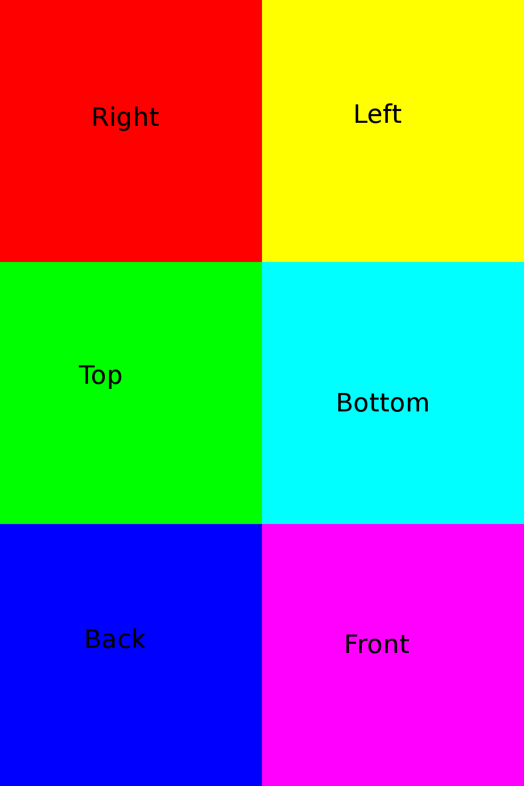
The whole shader can be converted to cycles nodes for use in Blender, but its a pain in the ass because some things are just missing (e.g. floor or sign functions). so have fun to whoever wants to implement it in cycles :P

Interior Mapping, The Theory

Ok so this is a little writeup on how interior mapping works. no images for now cause its late and im tired.

For those that have never heard of it, this is a technique to make rendering of many/endless rooms possible without having to actually generate the geometry for it.

I will word this write up for use with normal GPU shaders, but the math behind it can also be translated to any raytracer. This will also only cover the mapping of simple rooms of the same size with no objects inside, but the techniques described here can be extended to also achieve that

Interior mapping (short IM) utilizes ray tracing to procedurally generate the illusion of rooms that are made of geometry. For this to work we need the following:
  • world position of our fragment/pixel that we are rendering. (WP)
  • view vector pointing from camera to the pixel (VV)
Now comes the magic, using WP and VV we can now cast a ray into our virtual interior space. We only have to figure out which wall is hit by our ray, and where it hits, then translate that to UV coordinates that we can use to determine the color of our fragment/pixel.

Because we are limited to simpler programming constructs in a shader i seperated the components of the raycast. Ill describe the process for the X axis, but it is the same for the other axes. Using the axis value i calculate which walls are enclosing it, so e.g. 0.5 is enclosed by a wall at 0 and 1 (or any other division that you wish). Using this information i think up two planes that i can intersect my ray with. e.g. one at 0 with the normal (1,0,0) and one at 1 with the normal (-1,0,0). we now have 2 endless planes(walls) that encase my one dimensional coordinate 0.5. I now use the same component from my ray and calculate the t in 0 = 0.5 + t * ray.x .this will tell me a factor that i have to multiply the ray with till it hits that wall. to accelerate this, i examine the sign of the rays component, to figure out which wall it will hit (forward or backward). this gives me t_x, which tells me the factor for hitting the wall in X direction. now i do the same for y and z to get t_y and t_z. the lowest of those will tell me which wall pair i am going to hit first, x, y or z. again using the respective component from the ray i can figure out if it will be the left or right (respectively up,down,front,back) wall. i then calculate the point of the hit using WP+VV*t using the respective t. i then use the other two components left in the vector to generate my UV coordinates for the texture. i can then return the color, and optionally the normal of the wall, because i know which axis im on, and which wall i hit, of which i know the normal.

So thats basically it. you trace a ray to figure out which wall you hit. the magic is in how its done mathematically. in my actual implementation i did the tracing using a 3dimensional form, which can be useful for tracing objects inside a room that are not at axis aligned. i used the general equation of a plane and a line, and plugged them into each other. then i used wolfram alpha to solve for t to get the t needed to intersect the plane with the line

keep in mind that this is only one of the ways to achieve interior mapping. there are others, its up to you which one you want to use

17 March, 2017

XRDP on Ubuntu-mate 16.04 on my Odroid C1

Im writing this mostly for future reference. I upgraded my odroids OS to Ubuntu-Mate 16.04. On the old one (lubuntu 14.04) i had xrdp configured, but kinda forgot how to use it. I couldn't get it to work, it would just not connect to the desktop sessions, or just disconnect me. So i figured that it might work better on the new OS.. well kinda. I installed it via "apt-get install xrdp" and was able to connect to it via RDP and also login using sesmanXVnc (sesmanX11Vnc always disconnected me for some unknown reason, but the normal one works fine too). Now the problems start...

After restarting, i couldnt reach the odroid. It doesnt connect to wifi without me being logged in locally =/ great. off to the internet! I eventually found a solution that worked for me. (i dont know if this step is necessary, but i didnt want to take any risks) I opened System>Preferences>Internet and Network>Network Connections, selected my wifi and clicked Edit. Then (after authenticating that) i went to the General Tab and enabled "All users may connect to this network".

The Step that probably fixed it was then to get the id of the wifi interface via ifconfig (which resulted in some rather long string, so i will abbreviate it with "enx"). then add a line to /etc/network/interfaces (just open it with nano). The line:

auto enx

this seems to tell linux to automatically enable this interface before loggin in.

Now i can just switch on the odroid without logging in, and it will connect to wifi, so i can then connect via RDP. Next issue: Connecting via sesman now fails, as the desktop server doesnt seem to run. Solution: just try connecting a second time. Yup the second time connecting with sesman suddenly works, while the first time will throw an error.

The linux environment still has a lot of shit to catch up on till i can call it an adequate desktop OS. No matter what you want to do with it, it always involves mysterious textfiles without any common structure that are all in random places. This is why windows has the registry. so you at least have one place with fixed datatypes for this shit. srsly linux get your shit together! ...o i guess you never will cause some neckbeards choke their snakes to their superiority while they waste years of their life just getting their system to work. I already have hobbies that eat my time. i dont need my workstation to eat even more of it

08 March, 2017

3D Printer PSU Repair

Finally i get around to another blogpost (tried it with video, not my thing. much easier to just take some pics and write text). I recently aquired a 3D printer kit. For those that dont know what that is: you have to build the whole printer from parts. Its a Geeetech Prusa I3 Pro <some letter, but i dont know which>. Now after painstakingly putting this thing together piece by piece, i even got it to work. But as expected there were problems.

The most obvious one was that i had underextrusion. The printer came with a 0.3mm nozzle, which was just too small for fast printing. So i went and bought myself a 0.4mm one, which now works.

While angrily leveling the bed and doing test prints over and over, i accidentally bumped the printer a bit, and its power went off. Damn, lets see if it works again later. *click*... *click click click* nope. The only thing i got was some coilwhine from the PSU. So i removed the screws that were holding the psu on the printer and let it rather forcefully land on the table the printer was sitting on.

Before disconnecting it, i decided to test it once again. *click*... and the printer came back to life. As it was now running again, i decided to not tinker with the PSU yet. Mostly because of laziness and wanting to do other stuff.

As im now approaching the point, that i got the hang of printing, i want to move it elsewhere. Cant have a loud 3D printer next to my bed when i have to print bigger parts. Before doing that, i decided to take a look at the PSU, to see if i can find a dry solderjoint. Here some pictures


seems the layout is kinda standard for these chinese PSUs. I think its mirrored though, in comparison to the one from previous posts. So we start at the left top.

You see a fuse, a cap, a common mode choke, then a rectifier, a switch to set 110V or 220V, then a really huge ceramic capacitor (big red) it looks like one of those standard ceramic caps, just much wider, then we have the 2 big elcos, at the end of the board the 2 switching transistors, in front of that the whole switching circuit, then in the middle the big switching transformer, to the bottom of that the shottky diode for rectification of the transformer output, then a big inductor and some output caps.

Now on the underside you see a lot of traces. I was looking for a dry solderjoint. On the top you see that big silvery part, that is the pad that leads from the diode to the inductor, and here is where the fault lies. When you zoom in, you can see that the 2 wires of the inductor have broken loose from the solder.


That is a relatively easy fix. So i put some more solder on the part and made sure to burn my fingers on the hot wire while holding the inductor from the other side get the two wires to properly connect to the pad.


Properly might be an overstatement, but i put it back on the printer and it works fine now :D


22 September, 2016

Blitzwolf BW-BR1 Bluetooth receiver teardown

im usually tied to my computer by a cable when using my headphones, so i wanted to change that. For that i ordered a cheap chinese bluetooth receiver. I went for the Blitzwolf BW-BR1 as i've seen the name in several placed, and hoped it would be at least a bit higher quality than any noname receiver. Today it came in the mail, and of course i tested it shortly after. *insert fail sound here* Its reception was miserable constantly losing connection when you held the device in your hand and complete signal loss when holding it close to your body (trouser pockets). Now i intended to at least grab this thing when getting up to close the window or otherwise move short distances from my computer, but in the current state it was basically useless for me.

So i wanted to know what kind of antenna it had. I consulted the internet if it had anything on a teardown with that device. Answer: nope. I decided to take matters into my own hands and open it to have a look myself. here it is before opening it
And here after i pried of the back with a screwdriver
You can see the nice chew marks there. Luckily they are mostly covered by the back cover. The cover was held in place by 6 pretty strong plastic pins. I pushed the case itself outside instead of pulling on the pins, so none of the pins broke of. We see the battery that is taped on the pcb with double sided tape. There are just testpoints under it, so no pic of that. On the left the phone jack and the + and - buttons. And on the right lower side of the PCB, we see the antenna, or at least one part of it. Lets open up the other side. The pins of the other side are reachable from here, so i didnt had to chew on the front cover.
Here we can see all the nice components and of course the other side of the antenna.
But wait a minute... i remember, that all the other bluetooth modules i looked at, only had the antenna on one side of the pcb, and the other side completely free of components and copper. Is this the reason why its reception is so bad? I dont know. lets solder on a longer antenna :D
scratched of the soldermask from the end of the antenna and placed copper wire conveniently next to it
soldered it on. Please refrain from comments on my soldering skills. I know they suck. Also i have a suspicion the leaded solder i bought does not contain any lead. Oh well, it makes a connection, and thats all we need (im pretty sure that botched piece of solder sprays radio waves all over the place, but meh).
back in the casing. I drilled a hole in there by hand using a 1mm hss drill.
Tadahhhh *fanfare*. Now i can at least hold it in my hand without loosing signal. But when moving behind a wall the same problem arises. Except in a tiny spot downstairs where i get wonderful reception when i just hold it right :D

Im using the bluetooth device that is built into my motherboard, so maybe that also contributes to a bad signal, as its encased in a metal cage. But i dont want to solder around on that. Mostly because im too lazy to get it out of my pc. Maybe i'll get a bluetooth dongle and solder an antenna on that in the future.

16 September, 2016

Cheap Chinese 24V 15A PSU from ebay

So i got this PSU here from ebay for an insanely cheap price of 21.91 € (that includes shipping). Usually this PSU would've cost me 10-15€ more (even from china). I was hesitating for a while, cause it seemed too good to be true, and the bad reviews of the buyer sounded a bit nightmareish. In the end i decided to go for it and see what i end up with. The picture of the listing depicted a dented, but otherwise functional, PSU, so i figured these might be units with shipping damage, that cant be sold for a higher price. And indeed when my PSU arrived, the acrylic cover of the terminals fell off. The little pins that held it in place were broken off. But the cover didnt had any information printed on it, so i didnt count that as a loss.

When getting a cheap item, i always inspect it before using it. so lets take the thing apart.
We get a 1 sided circuit board with through hole components. Key elements here are the switching transistors at the back(1), the switching controller(2), the switching transformers(3), the huge inductor(4) and the diode rectifier on the left(5). Now how do you test for overheating components? Some people try a laser thermometer, but i find that very tedious and not satisfying at all. So i got myself a thermal imaging camera in january 2016 for exactly that purpose. Lets take a first look at the device seconds after plugging it in.


Uhoh... that doesnt look good. We have a ton of hot components here. Lets investigate further:

i luckily found a blog that already reverse engineered such a supply. The schematic is pretty close to what my PSU has, so i will tell you about the differences further down.
blog: http://imajeenyus.com/electronics/20151028_smps_variable_voltage/index.shtml
schematic: http://imajeenyus.com/electronics/20151028_smps_variable_voltage/s-400-12_supply.pdf


R41 (3K9): This is a smaller resistor. probably rated .25W.  It's directly connected to the power LED and is supposed to run the LED off from 24V. i let it be, as there are no components next to it that could fail due to its heat, and if it fails, the LED will die, and the led isnt vital to the project.


R16 (330R): A big 1W resistor wedged in between 2 caps. This is a bleeder resistor that should discharge the 24V filter caps. Now lets calculate the powerdrop going through it using this formula: P= U^2/R. so P = 24^2 / 330 = 1,745W. This is way over the resistors Rating. Now i dont have any 1W resistors, but i could put some higher value .25W resistors across it. Or even just one, as the PSU is supposed to be part of an enclosed appliance, and thus it doesnt matter if the 24V stay on there for a bit longer. Lets calculate a good value for a .25W resistor.

0.25 = 576 / R
R = 576/0.25 = 2304

So using a 3k or higher resistor should suffice.


R37 (22R): (Update: the fans speed is changing with the load that is applied to the PSU, so i dont have to change anything here) Again a 1W resistor. This one is in series with the fan. Looking at the silkscreen it seems like its in the wrong hole and a component next to it is missing. Looking at the schematic and the full image on the blog we can see that this component is a NTC thermistor, which should reduce its resistance with increasing temperature. Its a crude way to make a fan react to higher temperatures. With the current configuration the fan is idling at a low speed, and only revs up when the PSU is unplugged (probably a voltage spike in the fans supply). I am unsure if i should just bridge the resistor and let the fan run full speed, or change its value so i get a bit better cooling. Im going to measure the voltage on the fan pins with my oscilloscope to see if the resistor is actually also there for dropping voltage. Im going to use a voltage divider for this, as the scope can only display up to 20V and will cut of anything above that. Also the computer disconnects the usb oscilloscope when that happens, and it takes a few seconds to recover. Now i tested the voltage, and i forgot i had a x10 probe :P so no need for a voltage divider after all. But the voltage is at 20V, so i dont just want to bridge the resistor. Instead im going to add a buck converter, and with that i can properly adjust the fan's speed.


R2&3 (150k on the right): Here we have 2 small probably .25W resistors that are there for bleeding the 2 big 250V caps that are filtering the positive and negative rail (each ~170V when feeding 240VAC in the device). Lets calculate the power dissipated in them. P=170*170/150000 = 0.193W. this is still under the .25W that the resistors are rated, so i will leave them, especially as i need a fast discharge for these big caps when unplugging the PSU.

In the same shot we see R11 on the left and C5 on the bottom. C5 is a small ceramic cap, so i just hope it can tolerate the heat


R1 (680K): This resistor is meant to bleed out the capacitor C4 that is across the AC line, so you dont get zapped by several 100 Volts. It gets hot, but again not close enough to other components to bother changing it. Also the bleeder resistors of the main caps will take care of C4 if this resistor fails.


R11 (1K5 on the left): This one is a mystery to me. Even with the schematic i have no idea what its purpose is. But it also gets searing hot and seems to be an important part of the circuit. The thing im going to build is intended to run ~14 hours a day for years. cooking the PCB and its components around it is not acceptable. I cant afford to let this resistor fail eventually, i will have to replace it. Probably with several higher value resistors.

now that we have sorted through these hot resistors lets look at another problem. Before i disassembled it, i plugged it in and moved my finger across the case. i felt a vibration. this means there is a voltage on the casing. when measuring it using a voltage divider made from 2 10k resistors it stopped, so grounding it with 20K is enough to eliminate that voltage. The reason why this voltage is there, was, that i only used phase and neutral to power the PSU. The PSU has a terminal for the ground wire, and the case is connected to that, so i guess when i put a 3 wire plug in there it should be fixed. The voltage itself is probably induced in the casing by the numerous magnetic fields that are generated inside the PSU.

Now for the missing parts: Im missing DB1. Here the part of the schematic with DB1:

i redrew this part to show how my DB2 is wired.

The difference this makes is, that i only get a half wave rectifier for my 24V output. Now this PSU is supposed to give me 15A, and i wonder if a half wave rectifier is the job for such a high current demand. It might cause the switching controller to switch the transistors harder. Luckily DB1 can be replaced by a bunch of rectifier diodes, But i dont have a 15A one. Also i would have to place some jumpers on the board. As you see C20 and R25 are also missing in my sketch, but they are still present on the board, they just go nowhere. Also yes C17 and R26 are wired the other way round. I know this doesnt make a difference, but i wanted to show that here too.

The next missing part is the NTC thermistor that should regulate the fan. In his PSU its put inside the inductor. I would personally put the thermistor somewhere over the switching controller and all that, cause those components are much more sensitive than the inductor.

I Also want to mention my PCB is labeled with a V2.0, which probably is the revision number. Maybe also a reason why his schematic is wired a bit differently

And thats it, a look at an extremely cheap psu. Lets hope it doesnt burn my house down. I probably didnt save money with this thing. I had to invest a lot of time, and time is money. If you only count the components i mightve saved something. As this is my hobby i dont count the time, so all in all: win? i will post a follow up when i replaced the components mentioned above

15 May, 2016

Motor Controller

In my first post (which has been ages ago) i showed you my styrofoam cutter which used my variac and 2 motors. Now i wanted to build a controller for the big motor for a long time. And i finally took my first steps in that project.

What we have:
Motor with tachometer at the back (a little generator putting out 8 pulses(sinewave) per revolution)

What we need:
Circuit that interprets the signal from the tachometer and calculates RPM and adjusts power to the motor depending on wanted speed.

This circuit needs several parts:
Arduino nano (or any microcontroller)
Convert sinewave of pulses into a rectanglewave (0-5V)
Power supply with zero cross detection so we can do phase control
Something to control the motor with the arduino

Lets look at the power supply first:
For our circuit we need positive and negative voltage, a stable 5V supply and a signal for zero cross detection. luckily i disassembled some old wall adapters which had transformers in them. The one i chose puts out 16V peak to peak. Now i need a circuit:

And this is it. At the top we have mains AC (which is 230V @50Hz here) which goes through a transformer and is then processed. I basically used 2 half wave rectifiers and connected them in series so i get + and - 8V. I then used the +8V and put them into a 5V regulator to get my 5V. i also directed the signal from the transformer directly into an opamp which creates a rectangle wave. This is then put through a diode, so we dont get any negative voltage to the arduino and through a voltage divider to go from the 8V down to a little under 5V, which is enough for the arduino to properly detect the signal.

Now for the tachometer part:
This is also a part where we need the + and - 8V. The tachometer is here depicted as a motor, but it puts out a signal depending on the motors RPM. now i measured the signal and it already got to almost 20V at 5000 RPM. So as the Opamp has an almost infinite gain, i decided to just put a 10 Ohm resister between the pins, so the voltage the Opamp sees is still very low and there is no risk of damaging it. Then again the output is put trough a diode and a voltage divider to get it to a 0-5V range.

Now lets get to the more difficult part:
How to control the motor? My initial plan was to use a beefy mosfet. It was rated at 15A @ 500V which should be enough for the motor. This solution would not require a zero cross detection circuit, but i would have to rectify the mains voltage (which would be 340V DC) and then use pwm to change the motors power. problem here is, that i have to connect my GND from my 5V circuit to the GND of the 340V circuit to switch the mosfet. or i would have to build an extra circuit that is isolated by an optoisolator.
I had this in my head for a long time, till i came across solid state relays. These are basically a relay, but can switch much faster, and dont degrade as there are no mechanical parts. So i want ahead and changed the circuit to what it is now. i added the zero cross detection so i can do phase control with the relay. phase control is basically PWM but with a very low period dictated by the mains frequency. You switch on the power during the sine and switch off at zero cross. The reason you do it this way is, that the Triac (the thing that is switching inside the solid state relay) can not be switched off as long as there is current flowing. With AC it always switches off at zero cross, as there cant be any current flowing, So i built the circuit around the arduino and did my first testrun:
The powersupply worked
The tachometer worked
The code on the arduino worked
... But the relay....

I tested the relay before i used it (not with the big motor). It switched on and off as expected. But there was something i was not aware of at the time. The relay that i bought (Fotek SSR-40 DA) has builtin zero cross detection. Which means it only switches on at Zero cross. The reason for this is, that you dont get any current spikes in your line and no electromagnetic fields and what not. Now this was bad. The motor has a pretty high startup torque and jumps a bit when just switched on. Also its impossible with this to make lower RPM happen without a big load. So i began searching for an alternative. There are solid state relays without zero cross detection, but they are rare and therefore more expensive (ironic as they have less parts inside). So why buy a relay, when you can build one? Such a relay is basically an optoisolator, an LED, a triac and some resistors. And we dont necessarily need the LED.

So i bought a triac and some optoisolators on ebay. The optoisolators work fine, and it doesnt hurt too much when they are a bit off spec. But the triacs.... I ordered 2 BTA41800 which are rated for 800V and 41A RMS. The spec says it should have a resistance of maximum 10 milli Ohm. I tested one of them and it has a resistance of 200 milli Ohm (or even more, im still unsure). when testing it i put around 20W through it in a short circuit. 3.20 Volts at 5.10A(cant get more out of my lab power supply). This was DC power and the BTA is rated at 41 Amps RMS, so maybe thats also another factor. Now i dont know the forward voltage of the BTA, so maybe i got skewed readings. i will try again with a resistor attached to see if it really is the BTA having such a high resistance. For those that dont know why this is bad:

The higher the resistance, the more voltage is dropped over the device when current flow through it. The resulting powerloss is the dropped voltage times the current flowing through it. So if you want to pump 40 Amps through such a small device you need a damn low resistance, or else you will just melt the component cause of the heat generated at that point.

Update on testing the triac:
I added a piece of an old heating element that i got a from a hairdryer to the circuit. with that i could pump >60W through it. 30V at ~2.3A. strangely the dropped voltage stayed(stood?) constant at 850mV. i tested with 13V at 950mA (amp values due to resistance of heating element) and got the same voltagedrop. does this mean the resistance gets lower with higher voltage? again this was done using DC voltage. Guess my knowledge just isnt enough to really understand triacs. I will just go for it and use the triac with the motor. If it blows up in my face i have to rethink again.


25 June, 2015

Workshop

Yay i did it! I finally got my own electronics workshop.
In this pic it looks a bit lonely and sterile, but its actually pretty cool to work with it. So lets come to its features:
On the left you see a big old CRT screen. Thats because the LCD i wanted to use is broken. So luckily i convinced my parents to not throw away this monitor back then (yes i never throw stuff away that still works, or sell it, because i know i will need it one day).

Behind the screen is the computer. Its a pretty old one. Only has a single core Celeron with 2.66 GHz. With Windows 8.1 it kind of works, but the browser has a hard time rendering websites if the cpu is used by something else... like my oscilloscope :D.

Yes thats right. I have an USB oscilloscope! It sits on the first shelf a bit right to the monitor (on some aluminium foil for shielding from the monitor. Actually that doesnt do anything but safe is safe :P). It cost me 100€ and can measure up to 250 KHz (well 250k samples a second). The special thing about it is, that it has 8 channels. So if i have to measure many things at once, im on the safe side. The downside of this is that the 8 channels are multiplexed, meaning that i only get half the accuracy when i use 2 Channels, and only a third when i use 3.

Next feature: The laboratory power supply sitting right next to the screen (red display). It can supply 0 to 32.3V at 0 to 5.1 Amps (actually 30V at 5A but they added some buffer to make sure it reaches the specified values). Well it can't give you a stable 30V at 5 A (it just cant do 150W output). It only cost 50 € so its okay (Good PSUs are expensive!). If i need Amps i can just get one of my old PC PSUs which then burn up the hood :P.

Lets get to the less technical stuff. Before i made this workshop, there was just the shelf on the bottom with all my crap on it. This was horrible to work with and i got backpain, because its too low to work on it when standing. So i got myself a nice Beechwood plate (250x50x18mm). I put 2 coatings of varnish on it, but i doubt it will hold up very long :P as you see im doing some heavy stuff on there. To raise the height of the working surface i used some 8x8cm pieces of wood that i glued together and screwed onto the plate.

Now for the shelves. Those are 2,80m long and 20cm deep. I can store all my crap on there that i dont need at the moment. If that is full i can still put stuff under the working surface :D. Oh i forgot to mention the outlets. we (my dad and i) placed 3 double outlets on the wall. the outlets can be controlled by a switch on the right (which you can't see in the pic). So when i build a tesla coil and it goes crazy i can use the switch to restore safety :P.

Thats it for the workshop. i can now do some nice electric stuff. I will probably post more entries on my progress. Next up is a controller for the big motor that you see there.

15 May, 2015

New Amplifier

A few weeks ago my old stereo that i had running every day for hours for over 10 years finally said goodbye. Its probably just a fuse, but it popped during normal usage, so i think its finally time to replace it (i already had to replace the big caps, because they were completely dead). The problem is, stereos cost money, and i dont like to spend too much at once. I got the old one from a fleamarket for 10 bucks, including 2 ceramic speaker boxes! It was an incredibly good deal. Sadly i managed to kill the woofer of one of those boxes (the voice coil detached from the cone). I tried reattaching it, and almost got it working... until i didnt detach it during a soundtest and the coil came loose again =/.

So for the last few weeks i had no audio, except my earbuds, and a smaller speaker that i directly attached to my soundcard. Luckily a friend found a very old amplifier in his attic and gave it to me. Its a 10W/15W 4-Channel amplifier. Of course thats not comparable to the old Stereo with its 250W each channel, but i set it up today and it works :D

As its an old amp, it uses old connections. my stereo hat cinch as inputs and and these clamps for the speaker cables. This one instead has 5 pole connectors for input and those old speaker connectors with the big, flat contanct in the middle. I had several of these speaker connectors in the basement, but i was lacking something that could connect my computer to a 5 pin connector.

For years i only had a mono connection to my stereo, because i had no cable with 3 leads available at the time i got it. But i found a 5 lead cable in the basement that i can use. Now i also had an old 5 pin connector cable around, that i got from a microphone for a big tape recorder. The microphone was essentially a little speaker. This connector had a little transformer inside the plug, which is probably there to protect the microphone from the high voltage from the tape recorder it came with. Also this microphone was mono, but had 4 leads in its cable. So i detached the transformer and resoldered the 4 pin wire to the connector. I used 1 lead for ground (pin 2), 2 pins for stereo play (pins 3 and 5) and one pin for mono record (pin 1). I didnt attach the last lead to my computer, because that made no sense. I just soldered it to the plug because i didnt want it to fly around. Then i soldered the cable of the plug to the 5 lead cable and the 5 lead cable to my stereo cinch cable that i had from my stereo, which i uses to connect my computer to the aux input (i now have 2 free leads in the 5 lead cable, for other uses).

My stereo had a contact switch that switched on a relay to power the stereo, but the old amp has some rotational switch for that. As i plan to use this amp for some time, i dont want to put too much stress on this switch (i switch it on and off at least once a day), so i attached an old lightswitch to the mains cable and put the amps switch in the on position.

I plugged everything together and it works :D

I now only have to put the new cable in the cable duct and everything is finished

28 April, 2015

Planning how to use the styrofoam cutter

Of course i didnt build the styrofoam cutter just for fun. we want to put styrofoam under our pool as isolation. But our pool is round. I could now go outside and lay out the platters and draw on them where to cut them, or i could use modern technology for this. Of course I used the latter :P

First i opened GIMP and created a new picture measuring 400x400 pixels (pool is 3.66m in diameter and we want a bit of overhang). I then drew a circle spanning the full width of the picture and placed rectangles to cover it. My styrofoam sheets are 0.5m x 1m in size so i used rectangles measuring 50x100 pixels. The result is this:


With this pattern i can propably save 4 or 5 of my 32 styrofoam sheets. Now i have to layout this onto my sheets. And here is the layout:


On the left the white stuff are leftovers. As you see i can save 2 sheets. But i managed to put one piece twice in a sheet, so i save a third one on the other half (wohoo 5 sheets saved!). The whole thing is symmetrical so i have to cut out each piece twice. Thats what im going to do the next days :D

little update: today i cut all the styrofoam sheets and of course i fucked it up and did not save the 5th sheet -.-. But otherwise it worked like a charm :D